Choosing the right Rubber Components in 2026 requires more than comparing prices, colors, or supplier catalogs. A seal that looks perfect on a sample table may swell in hydraulic oil, crack under ozone, or lose pressure after repeated compression. Material selection must match the real working environment.
Professor James E. Mark, a respected polymer scientist, stated, “The properties of polymers depend on their molecular structure.” This principle remains practical today. EPDM may suit hot water and weather exposure, while NBR often performs better with petroleum-based oils. FKM can handle demanding temperatures and aggressive chemicals, but its higher cost may not suit every application. Silicone offers excellent temperature flexibility, yet it may wear poorly under certain mechanical conditions.
The details matter.
A reliable decision considers temperature cycles, pressure, abrasion, compression set, chemical contact, tolerances, and expected service life. Engineers should request compound data, traceability records, test results, and clear compliance documentation. Supplier experience also matters, especially when components require custom tooling or tight dimensional control.
Still, no selection method is perfect. Laboratory results cannot reproduce every installation error, storage condition, or unexpected contaminant. I have seen technically strong specifications fail because maintenance teams used the wrong lubricant. That uncomfortable lesson deserves attention.
This guide explores practical ways to evaluate Rubber Components for modern equipment. It connects polymer knowledge with field experience, documented testing, and realistic risk assessment. The best component is not always the most advanced one. It is the one that performs consistently where it must.
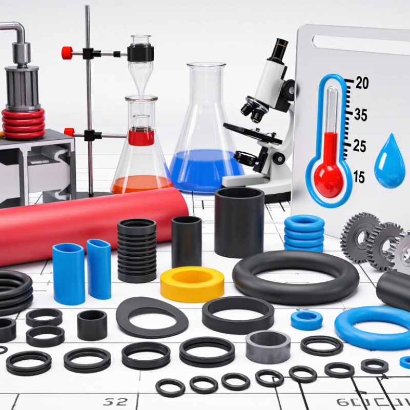
Define the application before choosing a rubber compound. Record pressure, vacuum, cycling frequency, and pressure spikes. Then identify every contacting medium, including oil, steam, coolant, cleaning chemicals, and compressed gases. A seal that survives oil may swell badly in hot water. Real service is messier.
Temperature needs equal attention. Map the complete range, from −60°C to 200°C, including start-up and shutdown conditions. Low-temperature compounds may remain flexible near −60°C, while high-temperature fluorocarbon or silicone compounds can approach 200°C. These limits are not universal. Pressure usually reduces the safe temperature range, especially during repeated cycling.
Use measured evidence, not only catalogue claims.
ISO 815-1 evaluates compression set after defined exposures, commonly 24 or 72 hours. A high compression set can create leakage after thermal ageing. ASTM D2000 helps classify rubber performance by heat, oil, and mechanical requirements. For gas service, NORSOK M-710 testing is relevant because rapid decompression can damage elastomers internally.
Ask suppliers for test data using your actual media and pressure. A neat table can mislead. Laboratory results may not match a seal squeezed unevenly inside a rough, hot groove. I would also test a small production sample before approving the full quantity.
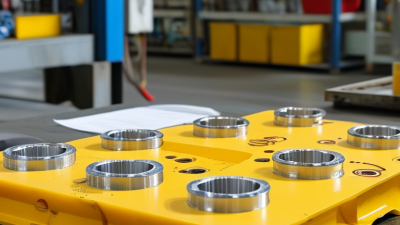
Choosing an elastomer starts with the fluid, temperature, and movement—not the catalogue name. Typical compound data place NBR around −40 to 120°C, EPDM around −50 to 150°C, FKM around −20 to 200°C, and silicone around −60 to 200°C. These ranges vary by formulation.
NBR usually performs well with mineral oils and fuels. It can swell in ozone-rich outdoor service. EPDM resists hot water, steam, weathering, and glycol fluids, but petroleum oils remain a poor match. FKM offers strong resistance to fuels, oils, and many aggressive chemicals. Low temperatures can expose its weakness. Silicone stays flexible in cold environments and suits clean, temperature-sensitive assemblies, yet it has limited resistance to tearing and many fuels.
Read the test method carefully.
Data from ASTM D471 and ISO 1817 support fluid-resistance comparisons through volume change, hardness, and tensile-property measurements. ASTM D2000 then helps classify rubber compounds by temperature and oil resistance. For sealing systems, ISO 23936-2 also highlights decompression and aging risks in demanding service. A 2024 International Rubber Study Group outlook reported continued growth in rubber demand, but market growth does not guarantee better sealing performance.
A neat table can mislead. Two compounds may share the same temperature rating but fail differently after compression, pressure cycling, or surface contamination. In practical selection, I would request actual compound data, compression-set results, and fluid-immersion results at the intended temperature. Small details matter.
Choosing rubber components begins with the application, not the catalog. In practice, I check temperature, pressure, media exposure, movement, and compression before selecting a compound. ISO 3601 helps control O-ring dimensions, tolerances, and suitable size identification. A small dimensional error can cause leakage after assembly. It happens more often than expected.
Tips:
Define the sealing conditions clearly. Compare the drawing with ISO 3601 requirements. Use ASTM D2000 to specify material performance, hardness, tensile strength, and resistance to heat or fluids. Its classification system creates a shared technical language between engineers and suppliers. However, an ASTM callout does not automatically prove suitability for every application. Testing under actual conditions remains necessary.
For products contacting food, drugs, or drinking water, review the applicable FDA requirements carefully. FDA acceptance depends on the material, additives, processing method, and intended use. Ask for current declarations, traceability records, and relevant migration or extractables data. Do not rely on a generic “FDA compliant” statement. It may be incomplete. A reliable supplier should explain test methods, lot control, and limitations without hiding uncertainty. I also recommend testing samples after aging, compression, and cleaning cycles. A component can pass a new-part inspection and still fail in service. Standards guide the decision, but field evidence should refine it.
How to Choose the Right Rubber Components in 2026?
Choosing rubber components starts with geometry, not catalog size. For static seals, target 10–30% compression across the working surface. Lower compression may permit leakage when surfaces vary or relax over time. Higher compression can increase assembly force, friction, and permanent deformation. A seal compressed to 18% may perform well in a clean, stable housing. The same design may struggle near 28% if installation is rough.
Measure the groove, mating gap, and rubber cross-section at operating temperature. Do not rely on nominal drawings alone. Rubber expands, shrinks, and changes hardness with heat, fluids, and aging. Specify tolerances for both the component and its housing. A practical design review checks minimum, nominal, and maximum stack-ups. At the minimum rubber size, compression must remain effective. At the maximum size, assembly should not tear the edge. Small radii and sharp corners deserve attention. They often create local stress.
Use controlled samples to confirm the calculation. Inspect compression after assembly, then test leakage or force under realistic cycling. Include storage time when possible. This is where assumptions become visible. I have seen designs pass room-temperature checks but lose sealing after repeated heat exposure. That weakness is easy to miss. Leave enough clearance for expansion, but not enough for extrusion. If results conflict, revisit geometry before changing material hardness. Better data may expose an imperfect tolerance plan before production.
| Component geometry | Typical application | Recommended static compression | Key geometry guidance | Tolerance focus | Design verification |
|---|---|---|---|---|---|
| O-ring, static axial seal | Flanges, end caps, covers and face-sealing joints | 15–30% of the O-ring cross-section; use the lower end for low-friction assembly and the higher end for improved sealing retention | Provide a controlled gland depth and adequate squeeze width. Avoid excessive gland fill because thermal expansion and fluid swelling can increase stress. | Control gland depth, flange parallelism, surface flatness and O-ring cross-section. Stack-up should keep the minimum squeeze above the sealing target. | Check minimum and maximum squeeze, gland fill, extrusion clearance, pressure, temperature and chemical compatibility. |
| O-ring, static radial seal | Sealing between a housing bore and a shaft, plug or cartridge | 10–25% of the cross-section in typical static radial designs | Use a rounded or chamfered lead-in to prevent cutting during installation. Keep the seal centered and avoid sharp groove edges. | Control bore diameter, shaft diameter, groove diameter, groove width and lead-in geometry. Include tolerance effects on diametral squeeze. | Verify installation stretch, compression, extrusion gap and assembly force at the full temperature range. |
| Flat rubber gasket | Large flanges, inspection covers, electrical enclosures and low-pressure joints | 10–25% of gasket thickness for many molded or cut elastomer gaskets; avoid compression that causes excessive relaxation | Use a continuous sealing land. Keep the gasket width adequate for the pressure and avoid narrow unsupported sections. | Control gasket thickness, flange gap, flange flatness, bolt spacing and bolt-load variation. | Evaluate compression set, relaxation, flange deflection, leak rate and retightening requirements. |
| Molded lip or perimeter seal | Battery covers, housings, doors and removable panels | 15–30% of the designed lip height for static environmental sealing | Use lead-in radii, anti-roll features or retention beads where needed. Avoid abrupt corners that concentrate strain. | Control lip height, groove depth, groove width, corner radius, parting-line mismatch and housing distortion. | Measure compression around the entire perimeter, especially at corners and near fasteners. |
| Rubber grommet | Cable pass-throughs, vibration isolation and edge protection | 10–20% radial interference or compression for retention and environmental sealing, subject to material stiffness | Provide a defined panel thickness range and a lead-in radius. Do not rely on excessive interference to compensate for poor hole quality. | Control panel-hole diameter, panel thickness, groove or flange diameter and rubber hardness. | Test pull-out force, cable bending protection, vibration durability and water or dust ingress. |
| Bonded rubber washer | Fastener sealing on metal panels and pressure-containing covers | 15–30% of the rubber sealing layer thickness under the installed fastener load | Use a sealing diameter wider than the fastener hole and prevent washer rotation where it could damage the rubber layer. | Control washer thickness, hole diameter, outside diameter, fastener seating and torque variation. | Confirm leak performance at minimum and maximum torque, temperature cycling and pressure cycling. |
| Custom molded static seal | Complex covers, irregular interfaces and integrated sealing profiles | 15–25% at the primary sealing bead; local geometry may require separate targets | Use uniform wall transitions, generous radii and defined flash or parting-line locations. Design for demolding and inspection. | Apply a tolerance stack-up to bead height, groove depth, mating-part flatness, alignment and mold shrinkage. | Validate with dimensional capability studies, leak testing, compression-set testing and environmental aging. |
Selecting the right rubber components in 2026 requires evidence beyond supplier data. Reliability claims should reflect the application, temperature, pressure, and fluid exposure.
Start with compression set testing at the highest expected service temperature. Place samples under controlled compression for a defined period. Measure thickness recovery after conditioning. A high value suggests poor sealing after repeated loading. Do not trust one test.
Swelling tests should use actual process fluids whenever possible. Record mass, volume, hardness, and surface changes before and after immersion. Small changes matter. Ozone testing exposes stretched specimens to controlled ozone levels. Inspect them under magnification for fine cracks, especially near edges and molded marks.
Wear testing should reproduce real contact pressure, speed, and movement. Use matching counterface materials and inspect debris during each interval. A laboratory result can still mislead. Field conditions often include vibration, dirt, and uneven loading. That gap deserves honest review. If a component passes three tests but fails after assembly, check installation force, surface finish, and storage history. The material may not be the only problem. Keep photographs, raw measurements, conditioning times, and deviations in the qualification record. Small testing errors can become expensive reliability assumptions.
The chart presents commonly used screening targets for rubber-component validation. Lower values are generally preferred for compression set, fluid swelling, and abrasion volume loss, while ozone resistance should show no visible cracks after exposure. Final limits should be confirmed against the application, compound, temperature, fluid, strain, and applicable test method.